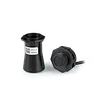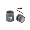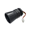


Reflective High-precision 3cm Blind Zone Ultrasonic Sensor A20
Ultrasonic probe adopts anti-water technology design, effectively reduce the problem of probe condensation, IP67 suitable for harsh environments.
Reflective High-precision 3cm Blind Zone Ultrasonic Sensor A20
Module : DYP-A20
Here comes the detailed specifications of DYP-A20 :
Item | PWM | UART | UART | Switch | RS485 | Unit | Remark |
| Operating voltage | 3.3~5 | 3.3~5 | 3.3~5 | 3.3~5 | 3.3~5 | V | DC |
| Static current | ≤5 | ≤5 | - | - | - | uA | |
| Average operating current | ≤8 | ≤8 | ≤8 | ≤8 | ≤15 | mA | |
| Peak current | ≤40 | ≤40 | ≤40 | ≤40 | ≤75 | mA | |
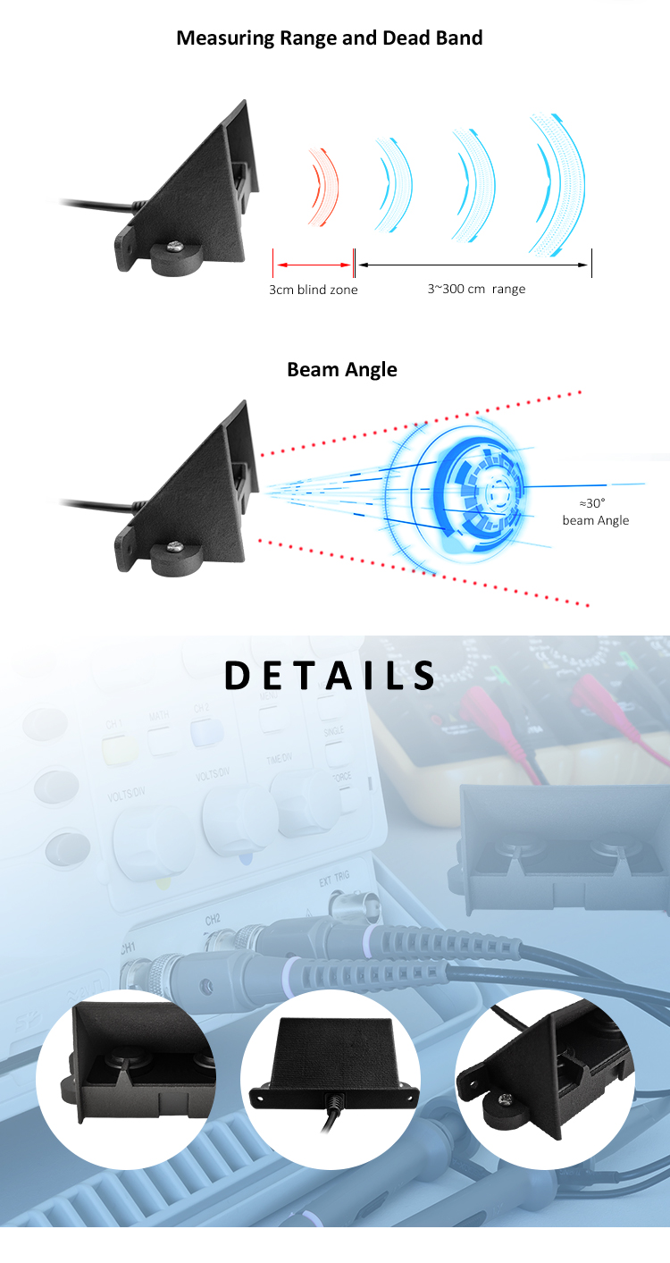
| Blind zone | 3 | 3 | 3 | 3 | 3 | cm | |
| Measuring range of flat object | 3~300 | 3~300 | 3~300 | 3~300 | 3~300 | cm | |
| Operating cycle | Controlled | Controlled | 100 | 100 | Controlled | ms | |
| Output interface | PWM | UART | UART | Switch | RS485 | - | |
| Accuracy | ±(1+S*0.5%) | ±(1+S*0.3%) | cm | ||||
| Temperature compensation | N/A | Support | - | ||||
| Beam Angle | ≈30° | - | |||||
Remarks:
(1)Typical data by testing with temperature of 25℃, humidity of 65%RH,power supply of 5V,and 100ms duty cycle;
(2)The temperature is 25℃, humidity is 65%RH, measured object is a 50cm×60cm flat carton, the transducer should be as vertical as possible. S represents the measurement distance;
(3)The measured object is the reference data obtained from the test of a φ75mm×100cm white PVC pipe with a distance of 100cm.
Rated Environmental Condition
| Item | Minimum value | Typical value | Max value | Unit |
| Storage Temp | -25 | 25 | 75 | ℃ |
| Storage Humidity | 65% | 90% | RH | |
| Operating Temp | -15 | 25 | 60 | ℃ |
| Operating Humidity | 65% | 80% | RH |
Remark:
(1)Environment temperature is 0-39℃,max humidity is 90%(Non-condensation)
(2)Environment is 40-50℃,max humidity is the highest at current temperature in nature.
Rated Electrical Condition
| Item | Minimum value | Typical value | Max value | Unit | Remark |
| Operating voltage | 3.1 | 5 | 5.25 | V | |
| 5 | 12 | 24 | V | RS485 Output | |
| Peak current | 40 | mA | |||
| 75 | mA | RS485 Output | |||
| Input ripple | 50 | mV | Peak value | ||
| Input noise | 100 | mV | Peak value | ||
| ESD | ±4K/±8K | V | Peak value |
Remark:
PWM output, UART Controlled output, UART Auto output, Switch output Contact wire and pin in accordance with IEC61000-4-2 standard.
Product Features
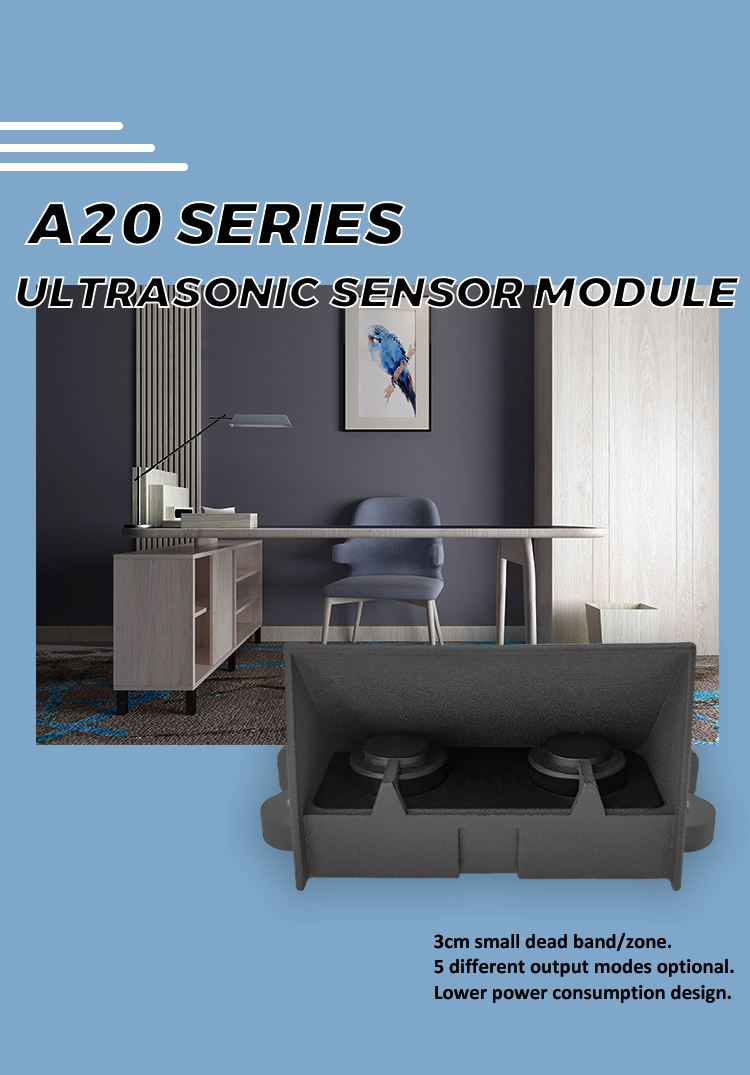
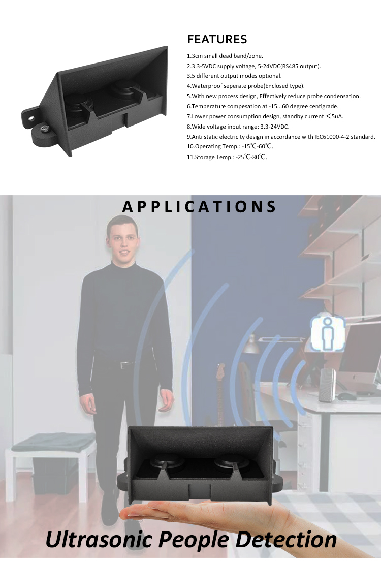
The DYP-A20 ultrasonic sensor boasts advanced features tailored for precision sensing. It features a 3cm small blind zone, enabling accurate detection in tight spaces, and supports a 3.3-5.0V input voltage (5-24V for RS485 output), ensuring compatibility with diverse power systems. With 5 optional output interfaces, it offers flexible connectivity for various applications. The closed split waterproof probe, combined with waterproof structural technology, effectively reduces probe condensation, making it ideal for humid environments. Operating reliably from -15℃ to +60℃ and storable between -25℃ to +80℃, it withstands harsh temperature ranges. Its low-power design ensures standby current below 5μA, minimizing energy consumption. Compliant with the IEC61000-4-2 standard, the anti-static electricity design enhances durability, making the DYP-A20 a robust choice for industrial and smart sensing needs.
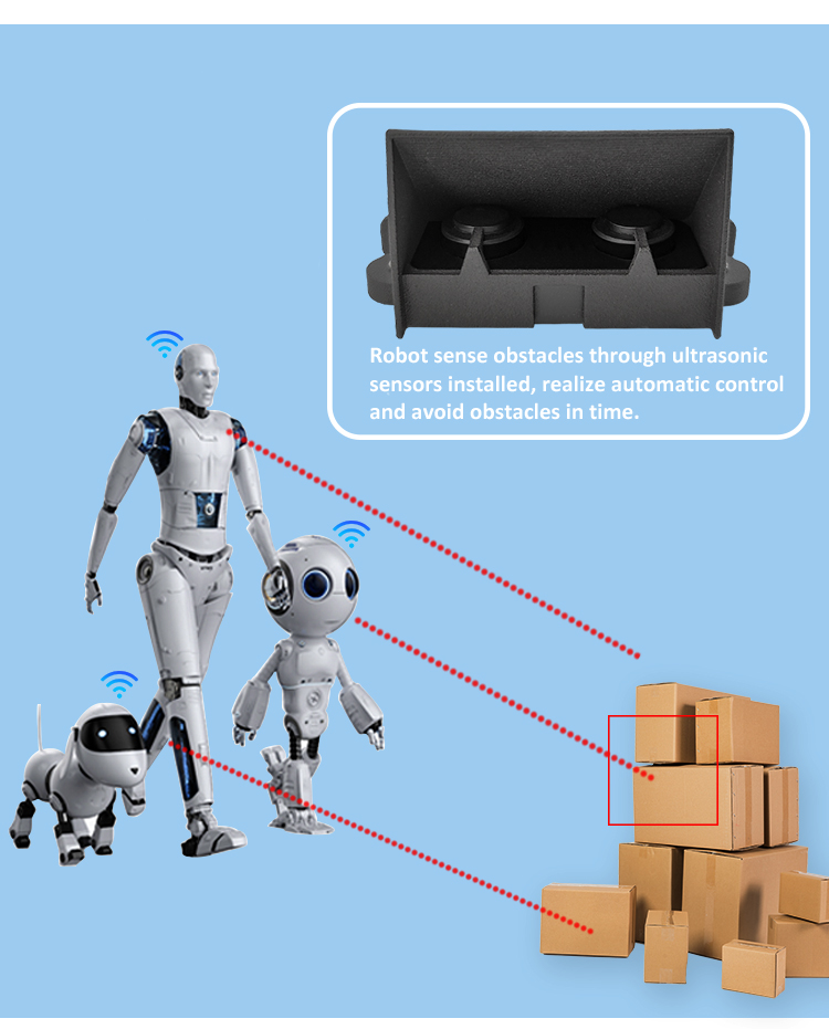
Scope of Application
Model Selection
The output format of this series of ranging modules is divided into 5 formats. If there are special requirements that need to modify the response time, angle, communication agreement etc., you need to communicate with our FAE engineers during purchasing.
| No. | Output interface | Model No. |
| A20 series | UART AUTO | DYP-A20NYUW-V1.0 |
| UART CONTROLLED | DYP-A20NYTW-V1.0 | |
| PWM | DYP-A20NYMW-V1.0 | |
| SWITCH | DYP-A20NYGDW-V1.0 | |
| RS485 | DYP-A20NY4W-V1.0 |
Notice
(1)The company reserves the right to change it and update the functions without prior notice.
(2)Please pay attention to structural tolerances when designing.Unreasonable structural design may cause transient abnormalities.
(3)Please pay attention to the evaluation of electromagnetic compatibility when designing. Unreasonable system design may cause malfunction of the module.
(4)When it comes to the application of the module limit parameter boundary,you can contact our engineer to confirm the relevant precautions.